Game Gear VA0 - 5
Console status
| Date | Power | Sound | RLB | Game operation | Screen |
|---|---|---|---|---|---|
| 2024/10/27 | ❌ | ❌ | ✔️ | ✔️ | ❌ |
Console details
- European Game Gear received from JamQue
- It came with replacement capacitors and gamebit screw was already unscrewed
- The battery contacts sleeve was also removed from the console
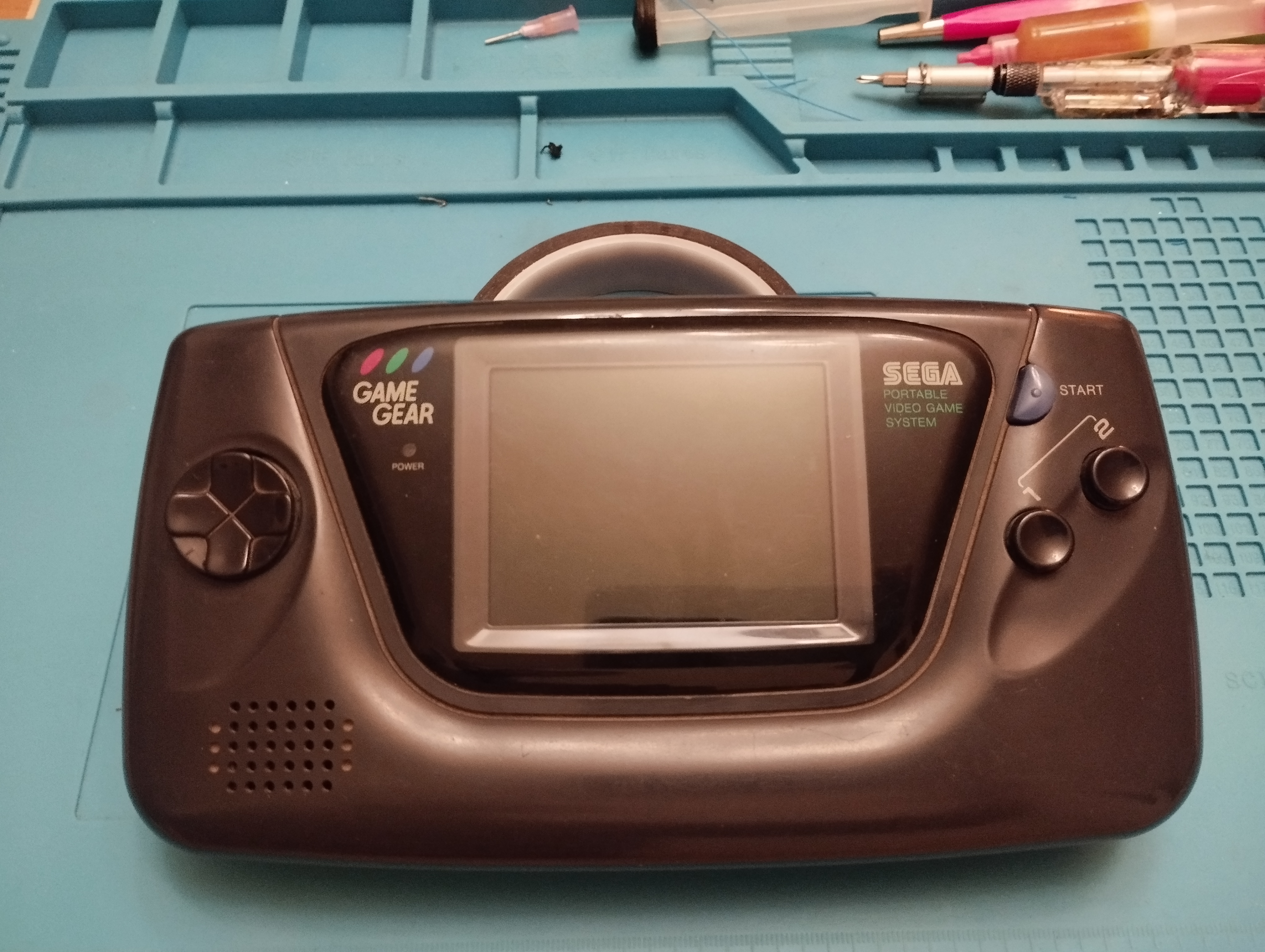
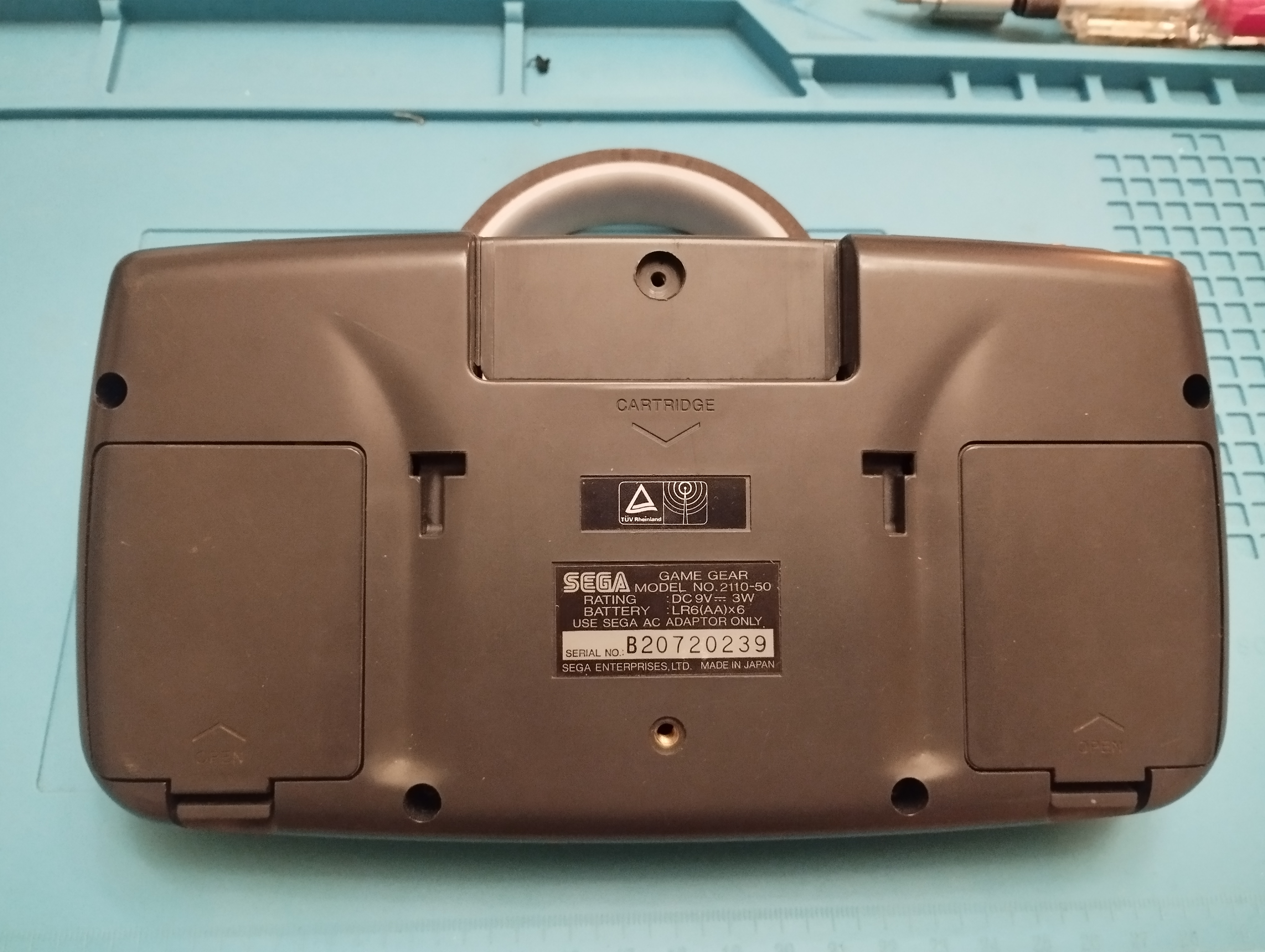
Specs
- Model Number: 2110-50
- Serial Number: B20720239
- Main board: 837-7996 (Twin ASIC)
- Power board: 837-7997
- Audio board: 837-7400-01
Overview
Visual inspection
Outside: the outside has visible scratches from usage but no cracks
Battery contacts: no signs of corrosion in the springs and plates
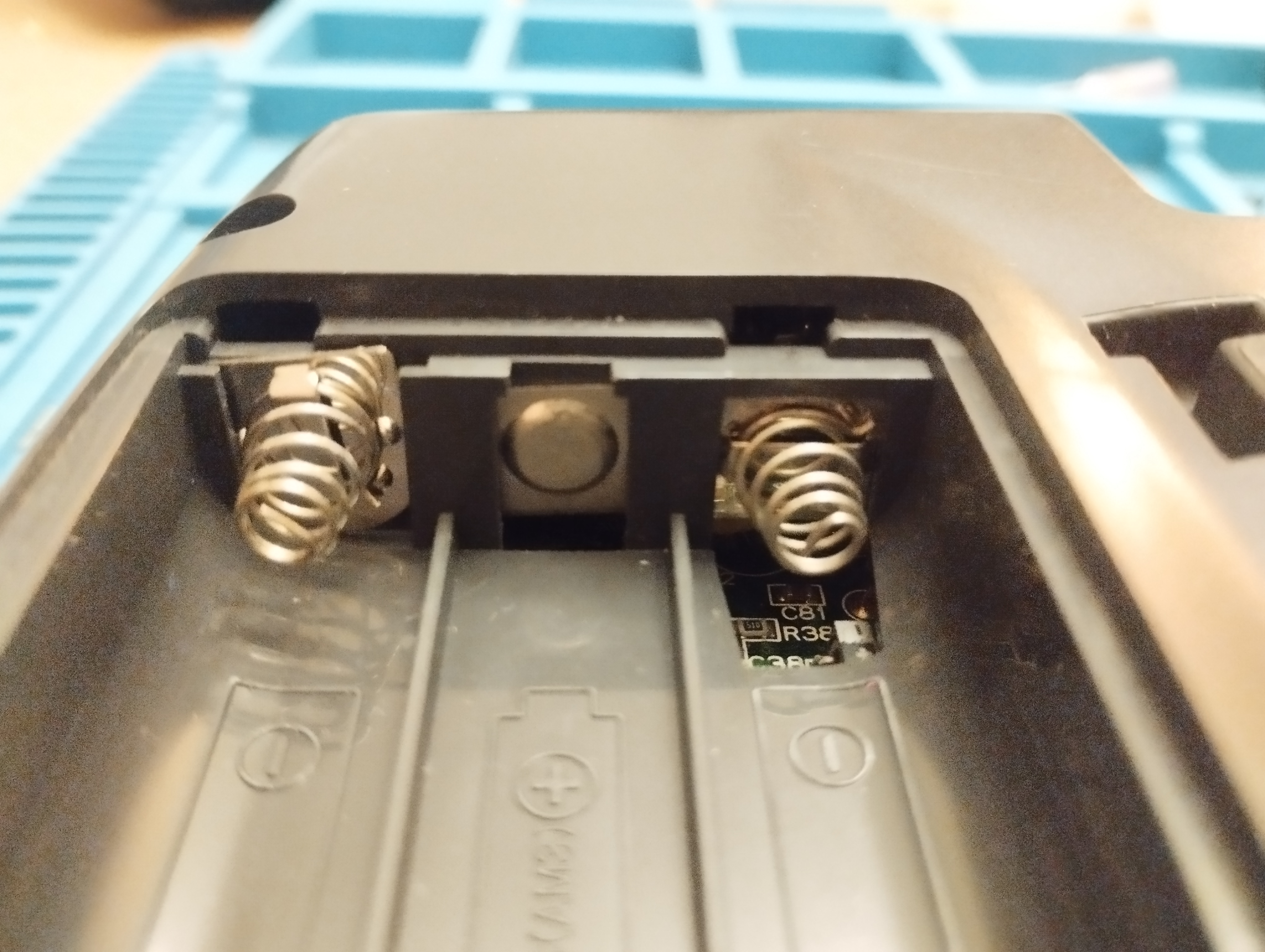
Main board - Top-left battery contacts 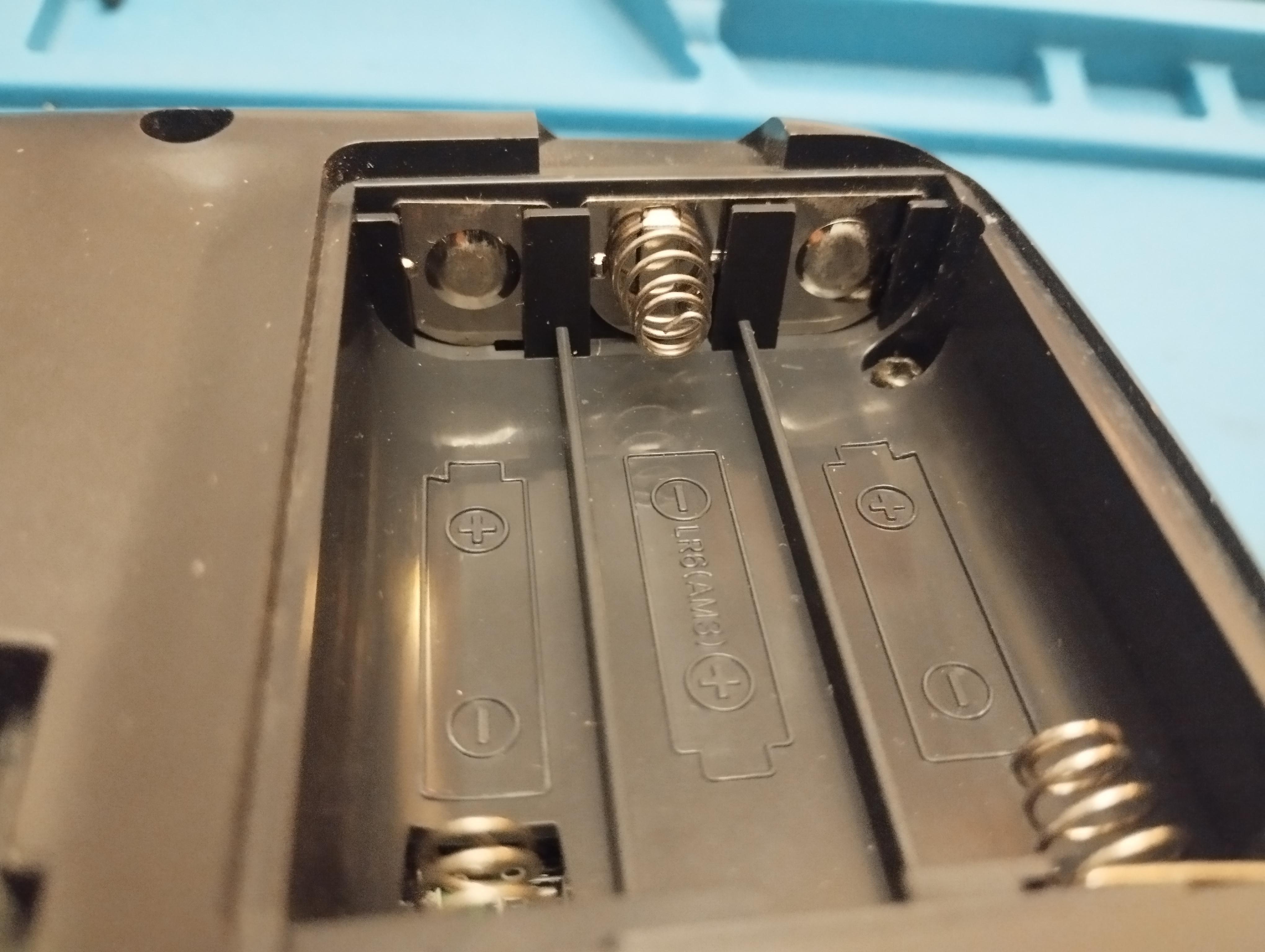
Main board - Bottom-left battery contacts 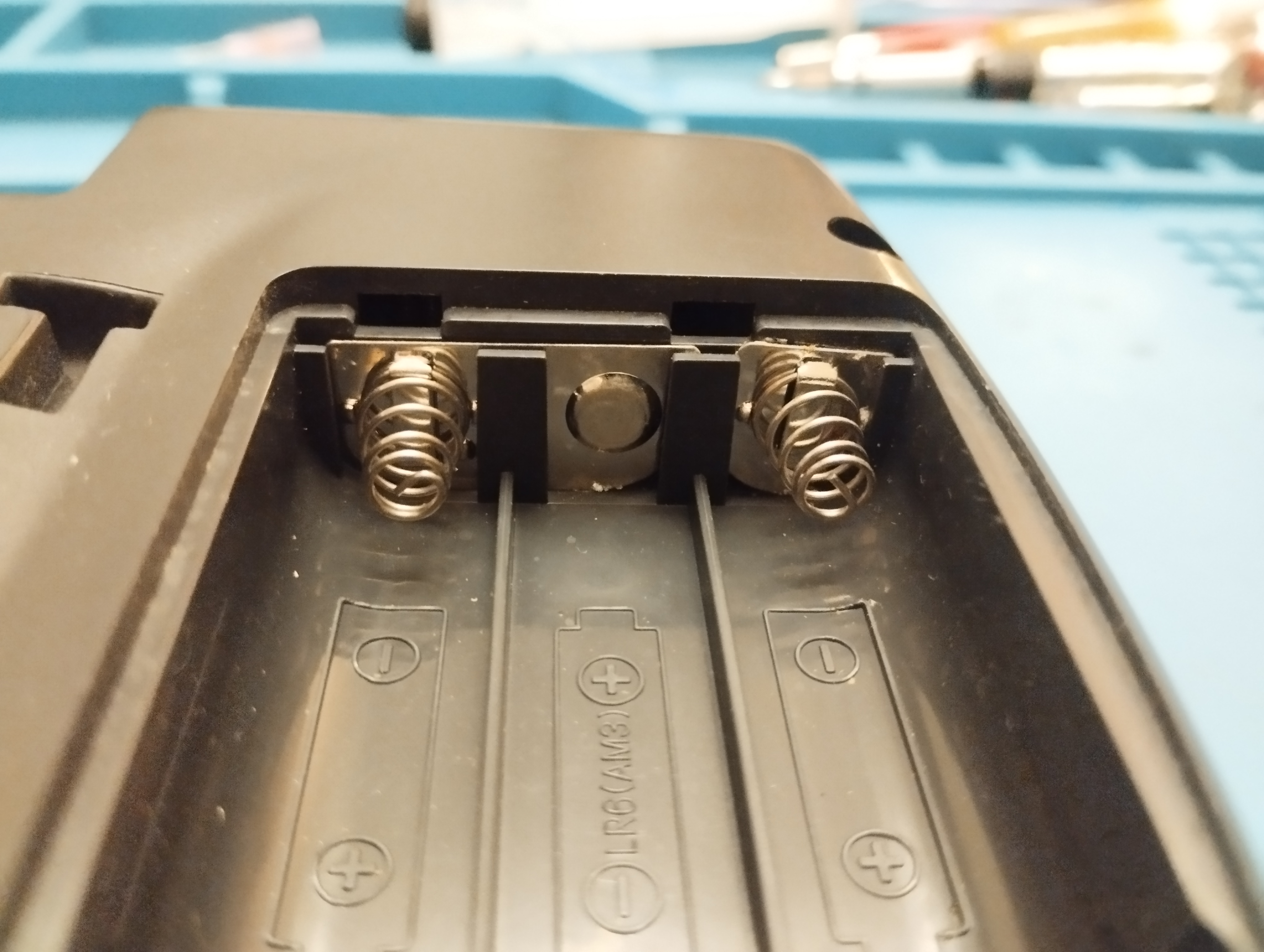
Main board - Top-right battery contacts 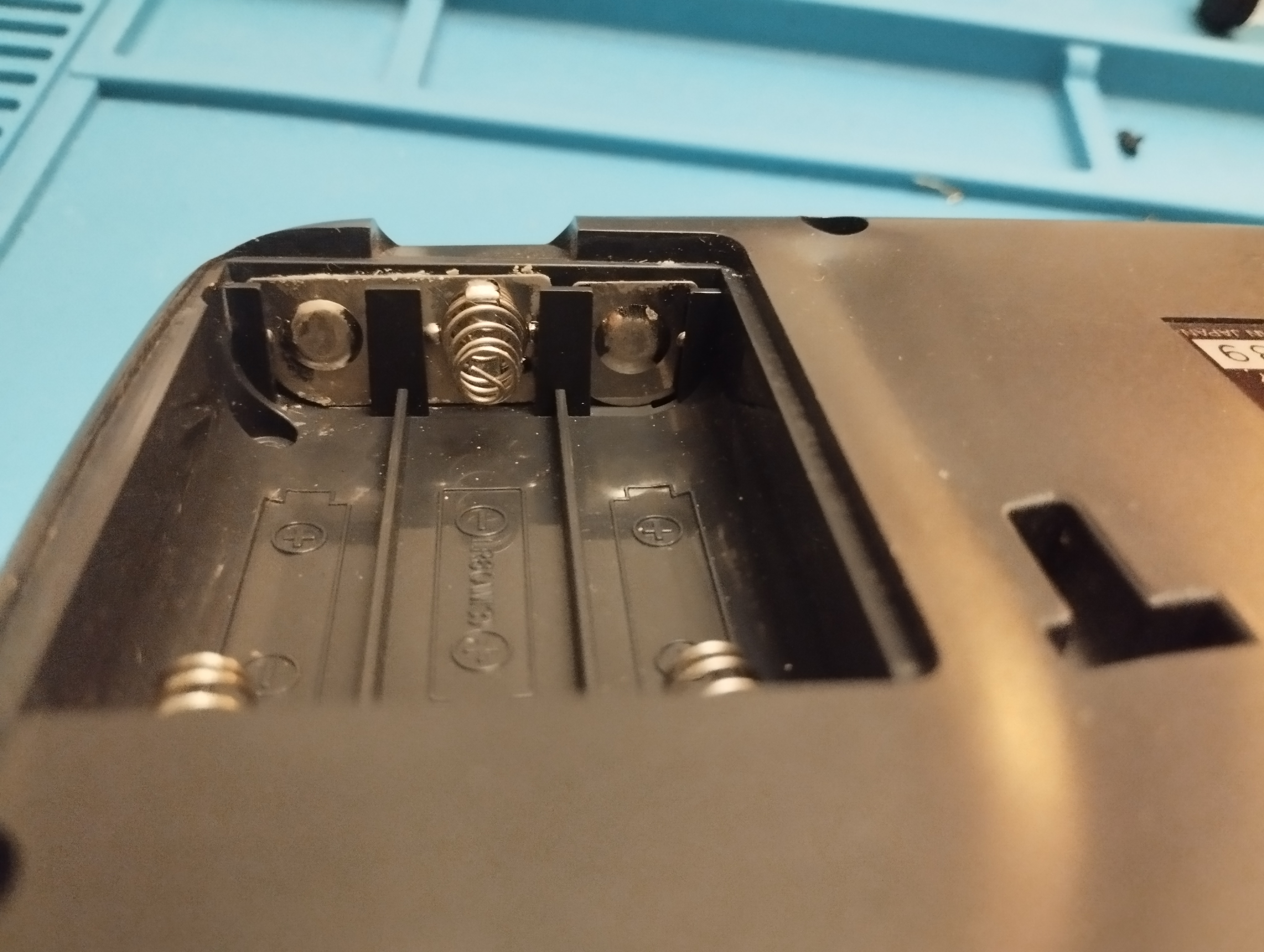
Main board - Bottom-right battery contacts Main board: capacitor leaks are visible on its legs, extreme precautions when removing and cleaning the pads. Also a lot of traces have been corroded, it’s possible that connectivity between layers is broken at some points
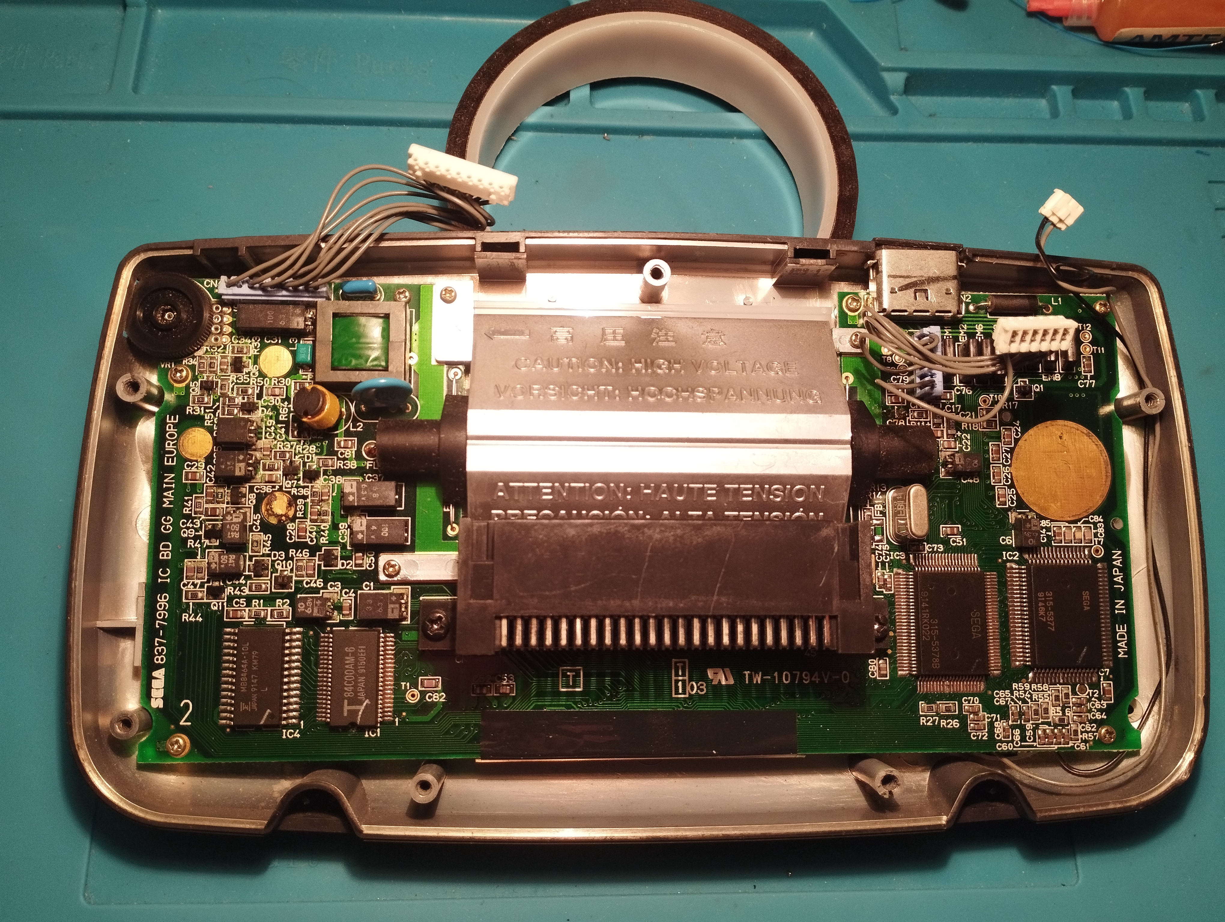
Main board - rear view, original capacitors 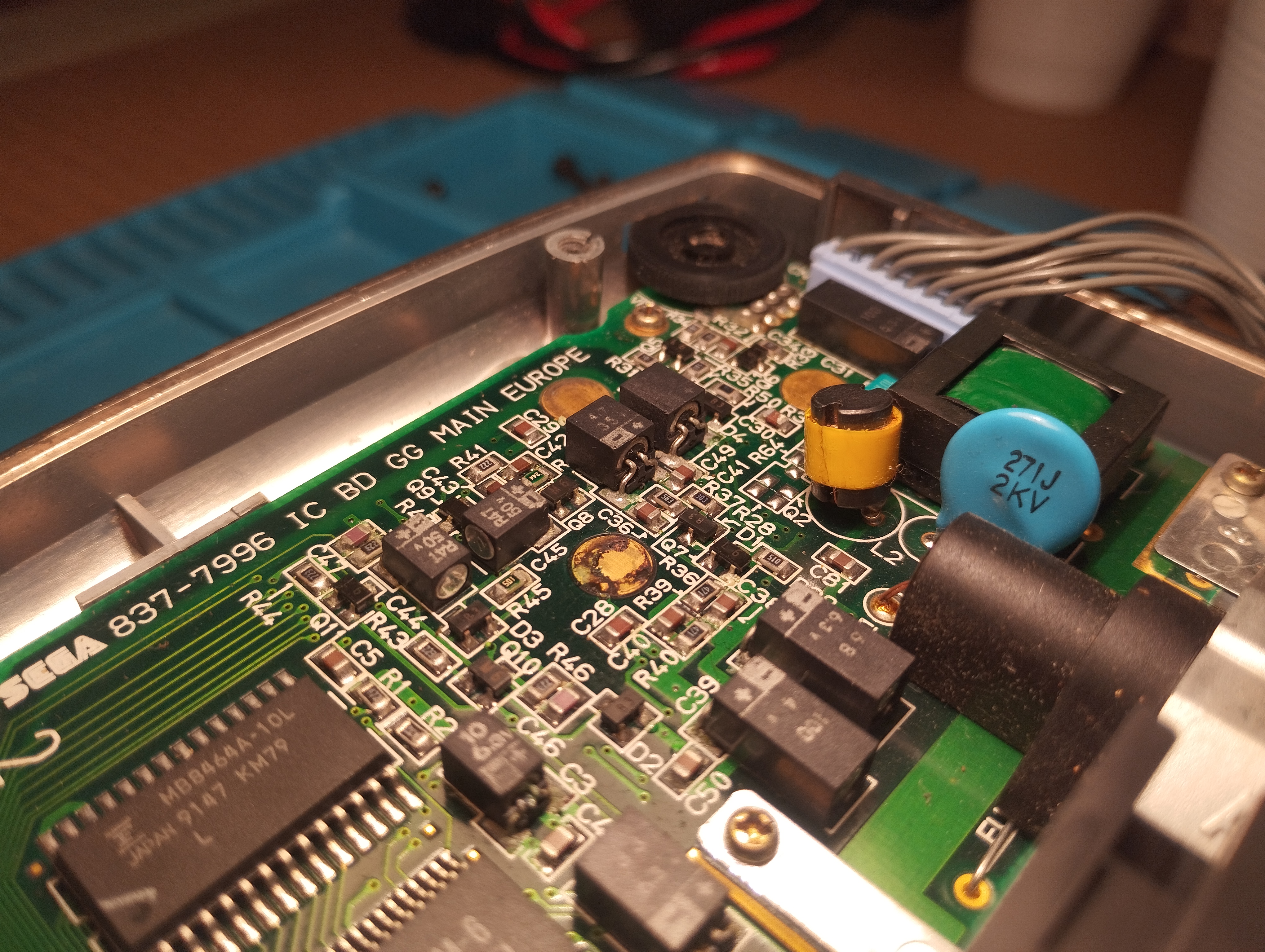
Main board - rear view, left side original caps. Visible leakage 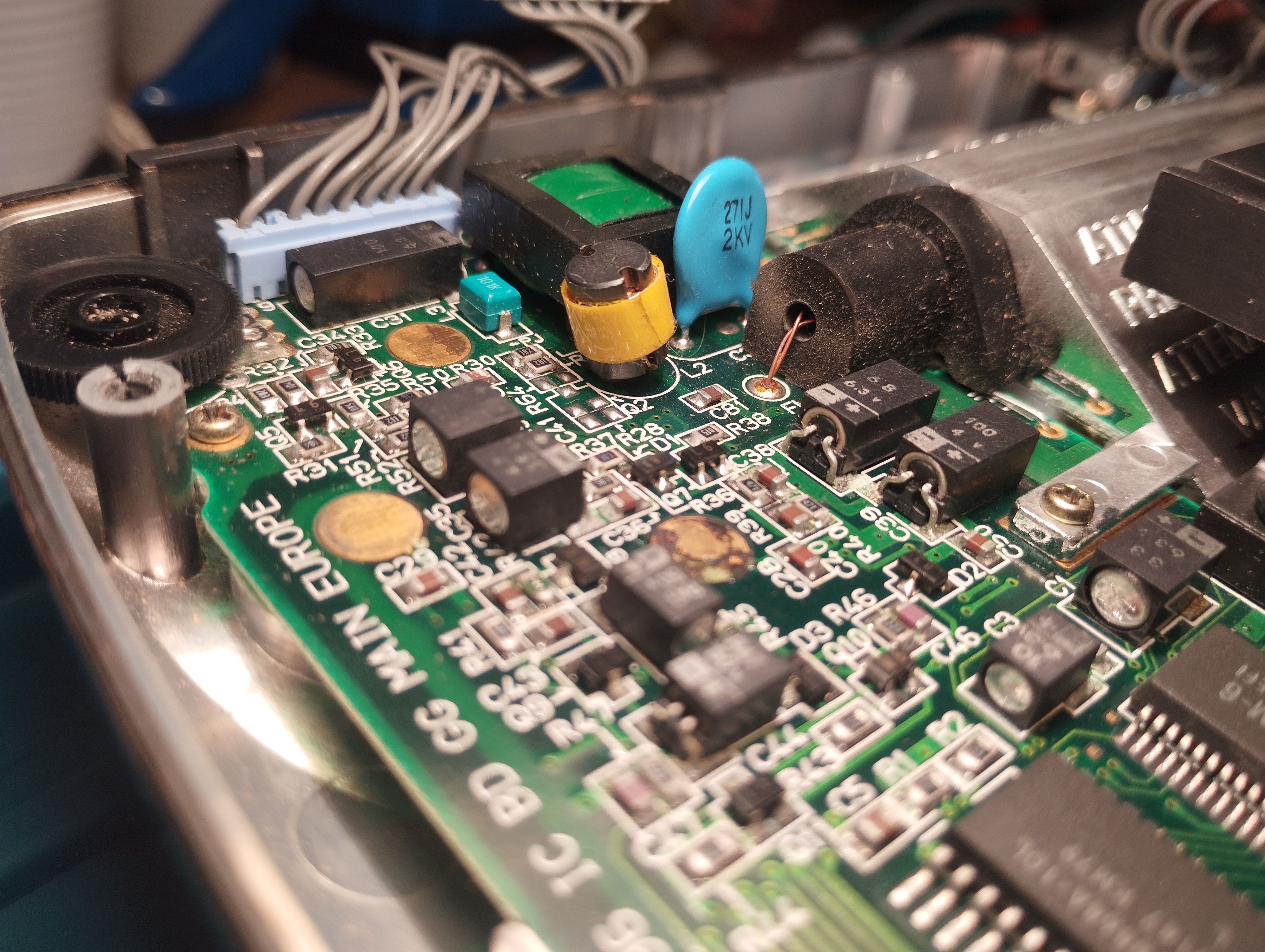
Main board - rear view, left side. Caps next to LCD 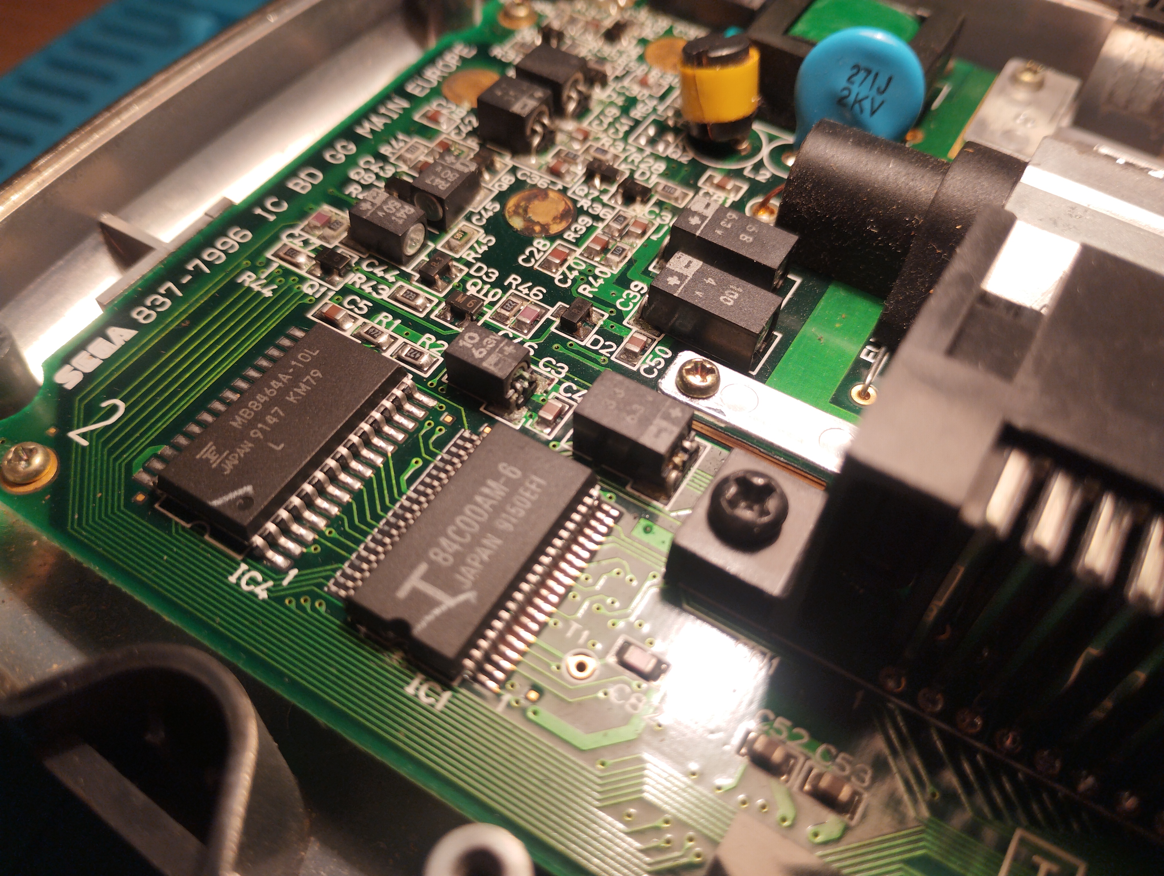
Main board - rear view, left side. Lower caps detail 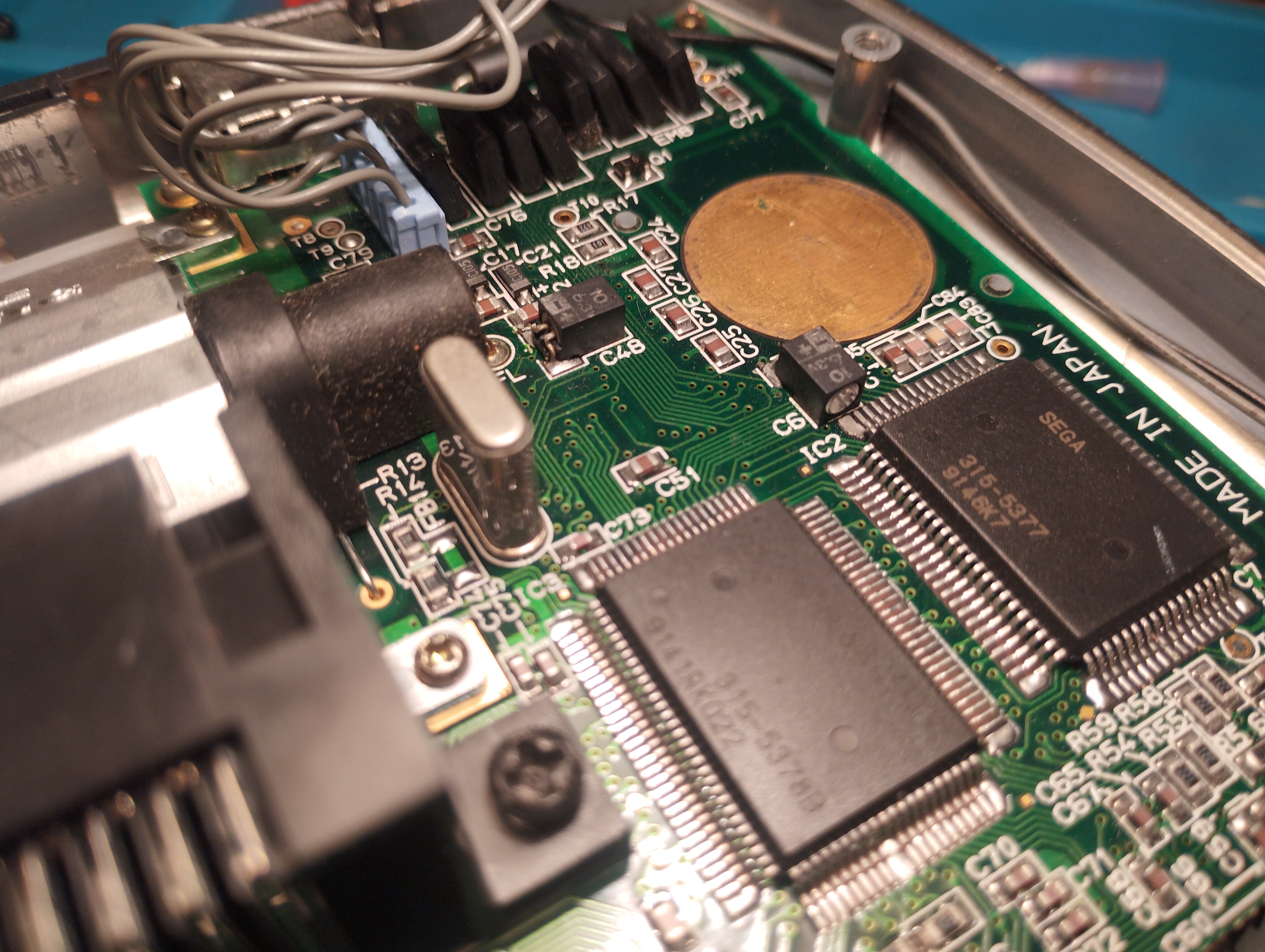
Main board - rear view, right side original caps 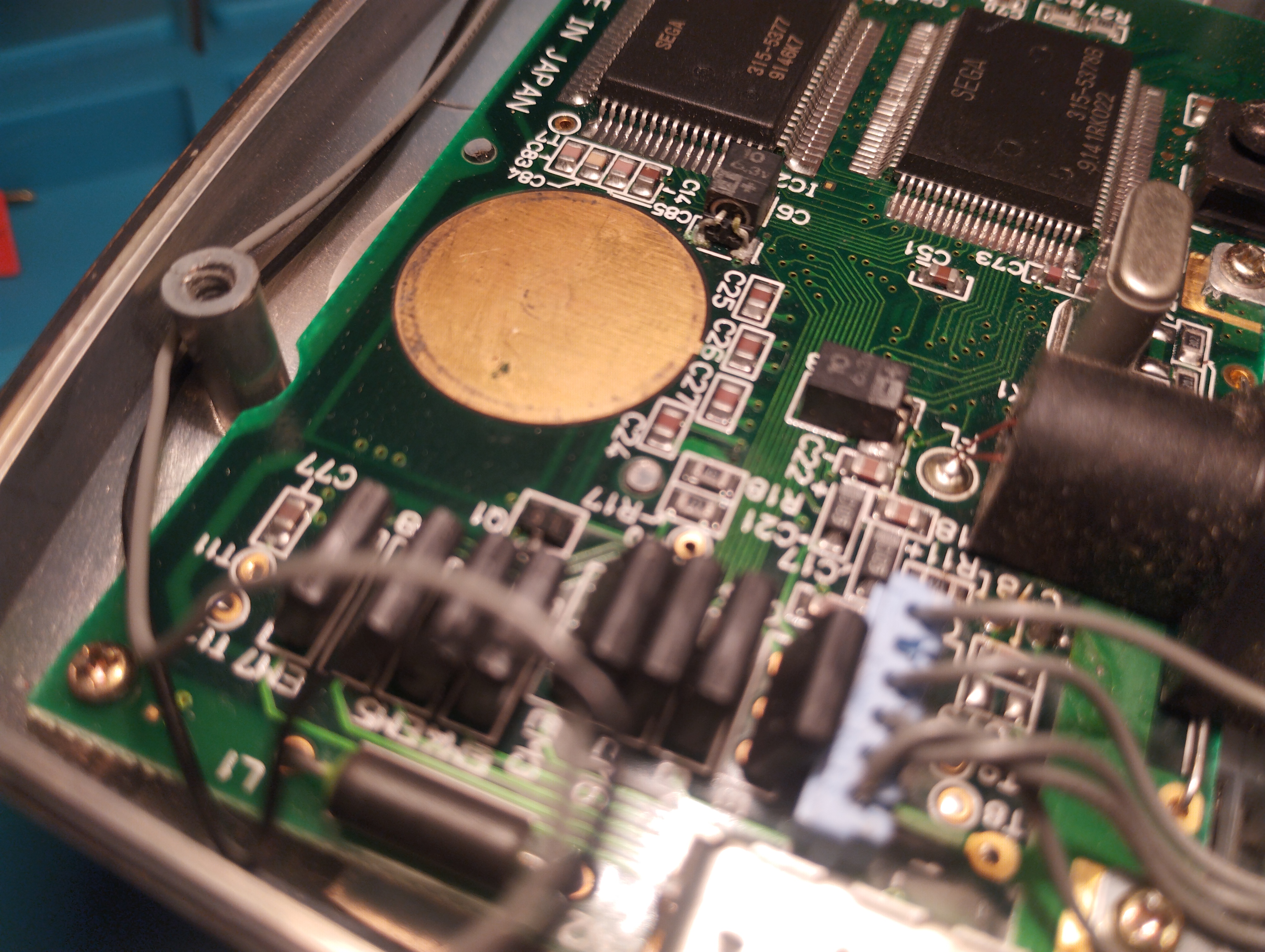
Main board - rear view, right side original caps. Leakage on C6 Power board: capacitors already replaced, voltage regulator seems to have been resoldered
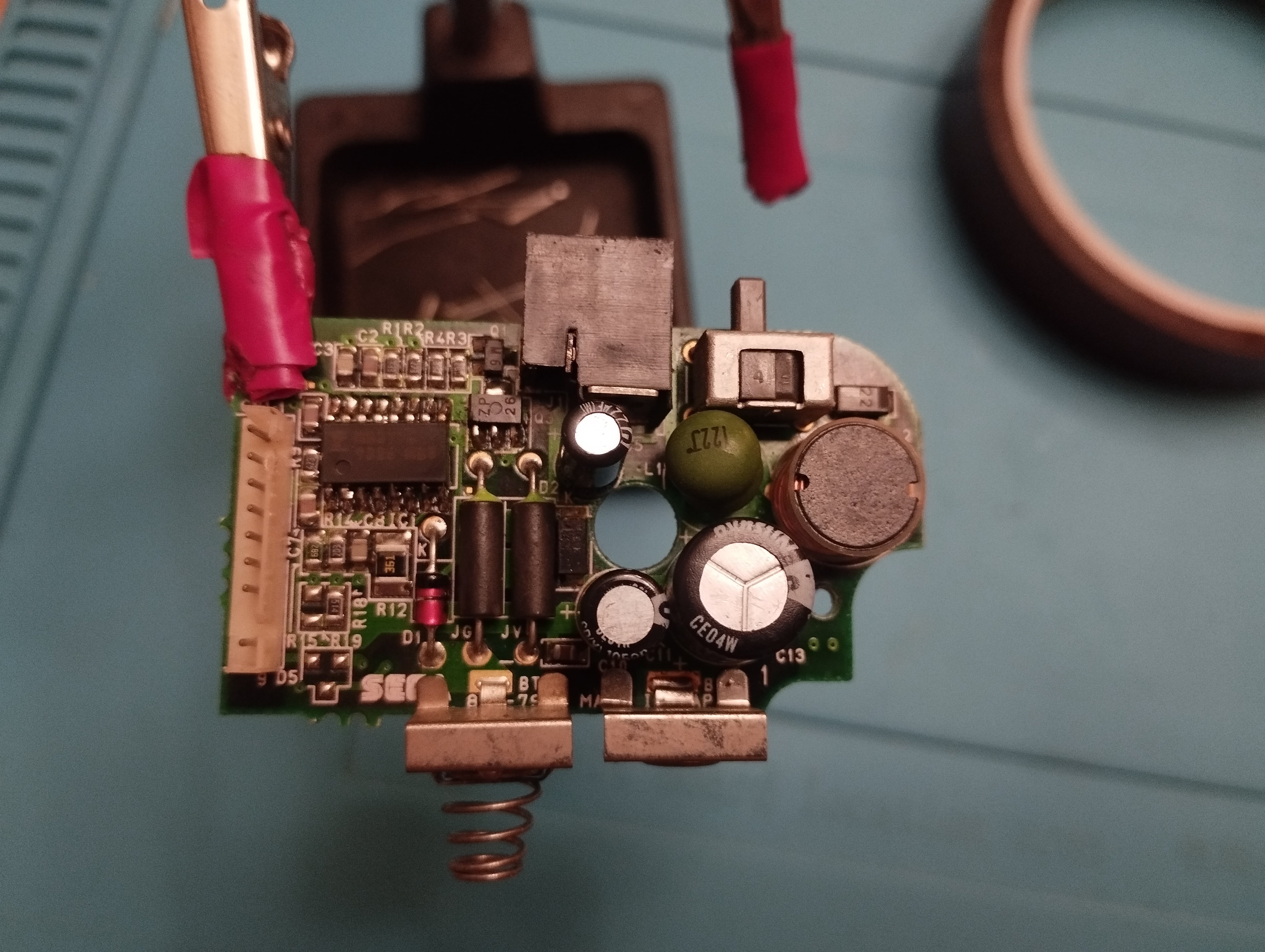
Power board - original capacitors already replaced. Voltage regulator apparently resoldered 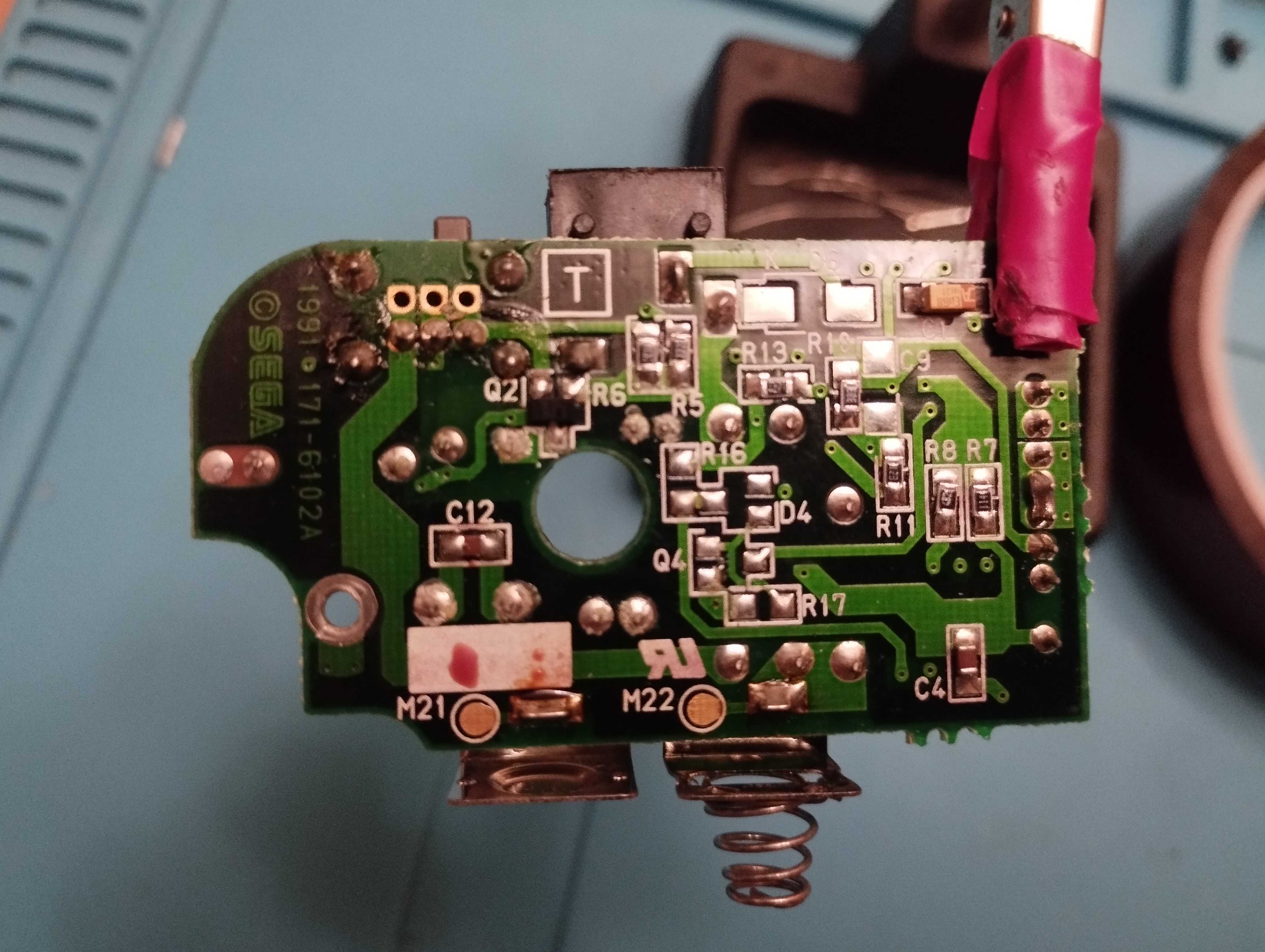
Power board - rear view Audio board: capacitors already replaced
Missing audio board pictures!
First boot
- Power LED turns on a few seconds and then it turns off
- The screen doesn’t turn on and there’s no sound either
Maintenance
2024/10/27: Recap
Following Retrosix’s wiki, the capacitors are replaced like this:
Power board
- Power board with existing capacitors doesn’t provide the expected voltages:
- 5V: 1.78V
- GND: GND
- 1.28V: 1.26V
- 9V (Battery input): 13.91V
- 34V: 1.05V There might be an issue with the voltage regulator as there are signs of being resoldered
Power board doesn’t properly provide 34V even after recapping. Using a functional power board for the tests
Using a functional power board the console reaches Red Boot Light without issues.
Removing some capacitors proved to be quite challenging, even with an electrical desoldering pump. The trick to keep the vias intact is to reapply new solder several times to mix old solder with new one. Flux is indispensable to help transfer heat on already old and dry solder as well!
If a leg is stubbornly stuck, use some desoldering wick with new solder and a lot of flux to remove the excess inside the via by capilarity. Rinse and repeat until the leg is free!
Also use the desoldering wick to free the hole from solder before putting the new capacitors.
Audio board
- Testing already soldered capacitors, it doesn’t seem to provide audio
Audio board still not working after recap! Sound is very dim from both speaker and jack, almost imperceptible due to the static noise. Using a functional audio board for the tests
–>
Main board
Main board loads games and plays audio when using working power and audio boards, and it reaches the Red Light Boot (RLB) state. Once verified that the console reaches the RLB state, it’s time to solder the new capacitors.
Before doing any heating work, and seeing the amount of corrosion in the zones near the capacitors, I decided to apply a generous amount of white vinegar to all of them and let it act during some minutes, while avoiding any leakage to the LCD.
C37 and C39 pads were heavily corroded. Further work on cleaning them was required:
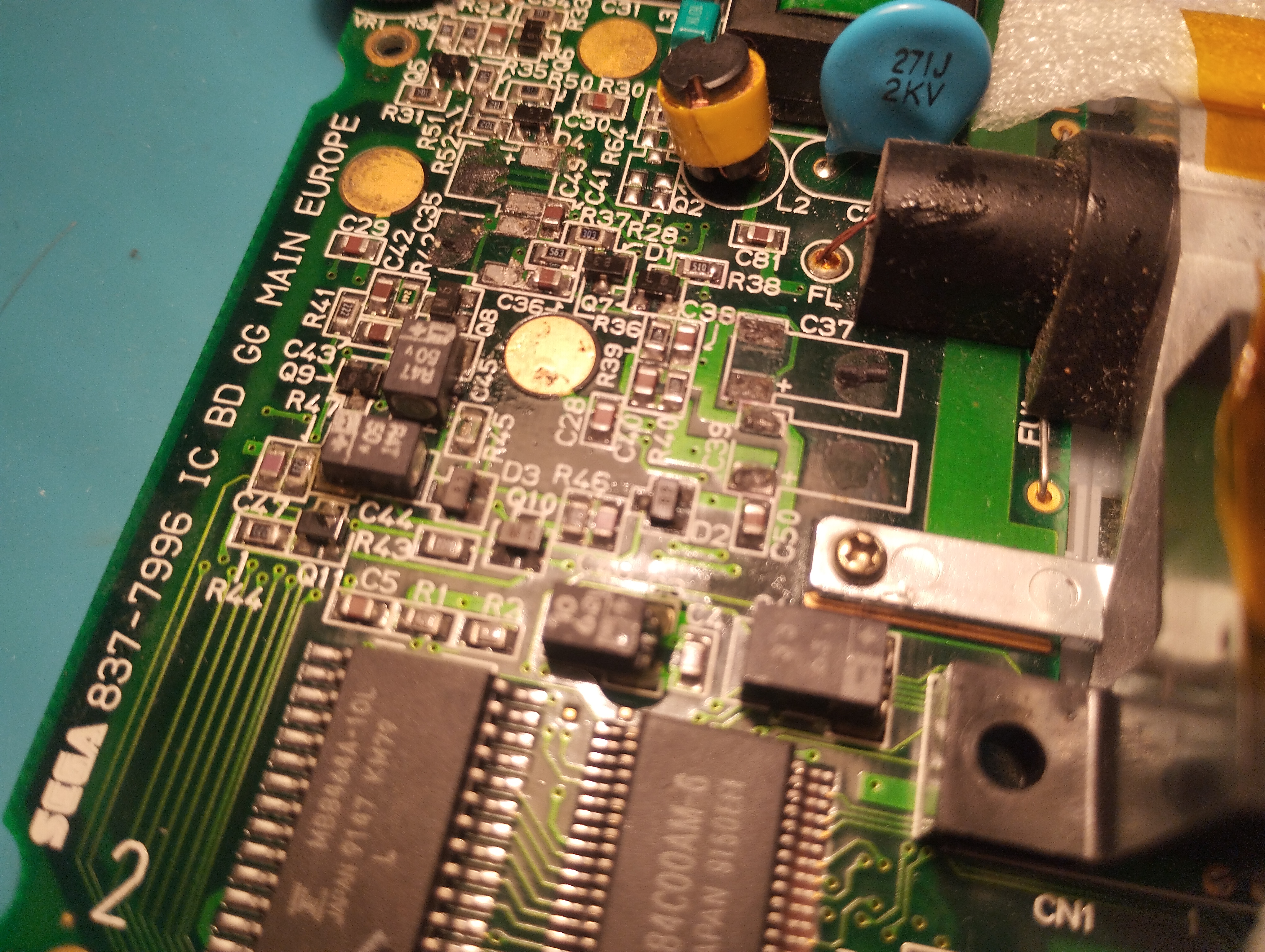
Main board - C37 and C39 corroded pads During removal of old capacitors, C6 right pad broke when using a desoldering wick to remove the remaining corrosion contamination and solder:
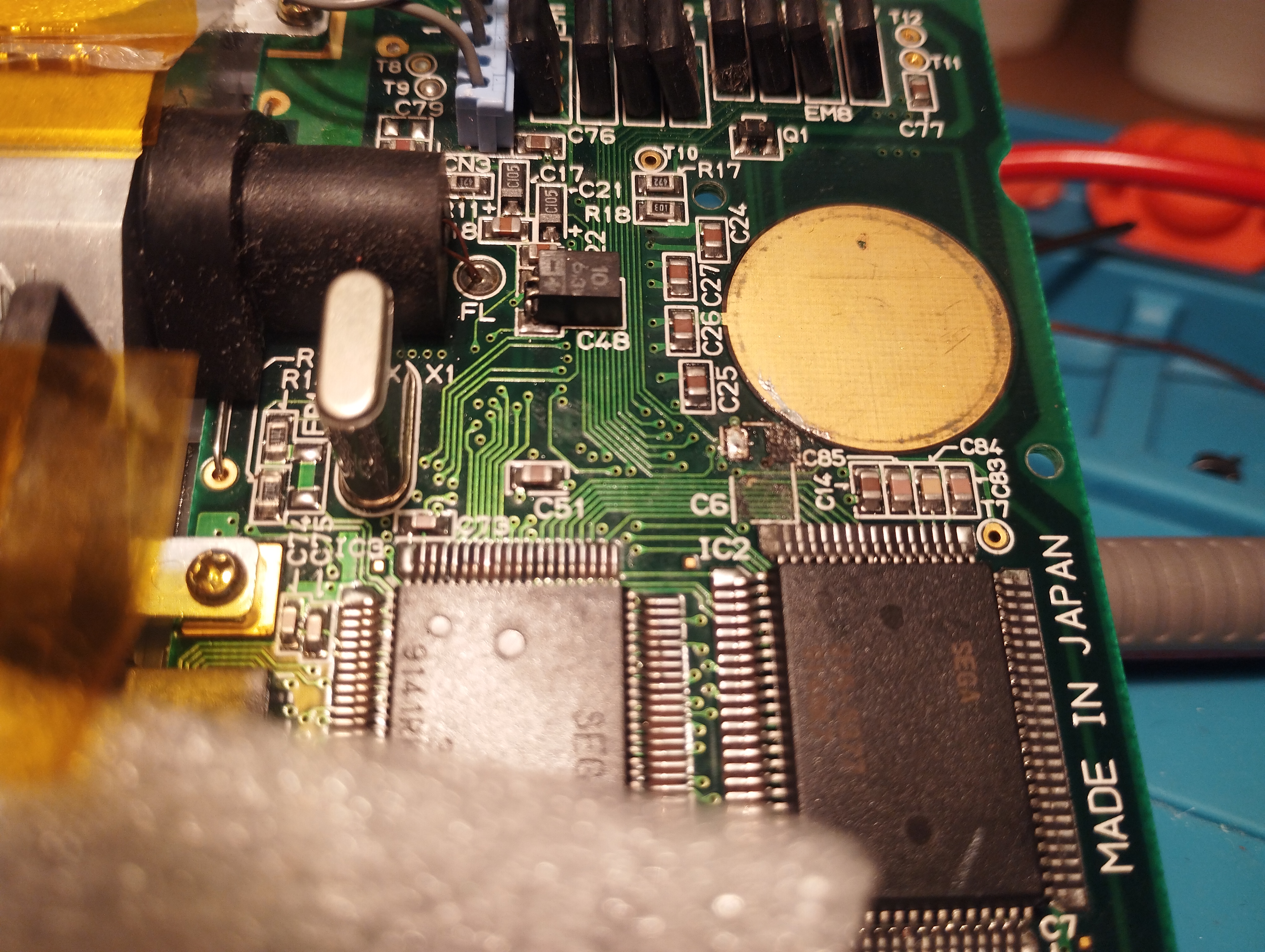
Main board - C6 pad destroyed
As with the previous VA-0 B0126683, these are the ceramic capacitors characteristics:
- All original capacitors rated lower than 1uF are replaced with 1uF/50V ceramic capacitors
- All original capacitors rated lower between 1uF and 10uF are replaced with 10uF/50V ceramic capacitors
- All original capacitors rated higher than 10uF are replaced with 100uF/10V ceramic capacitors
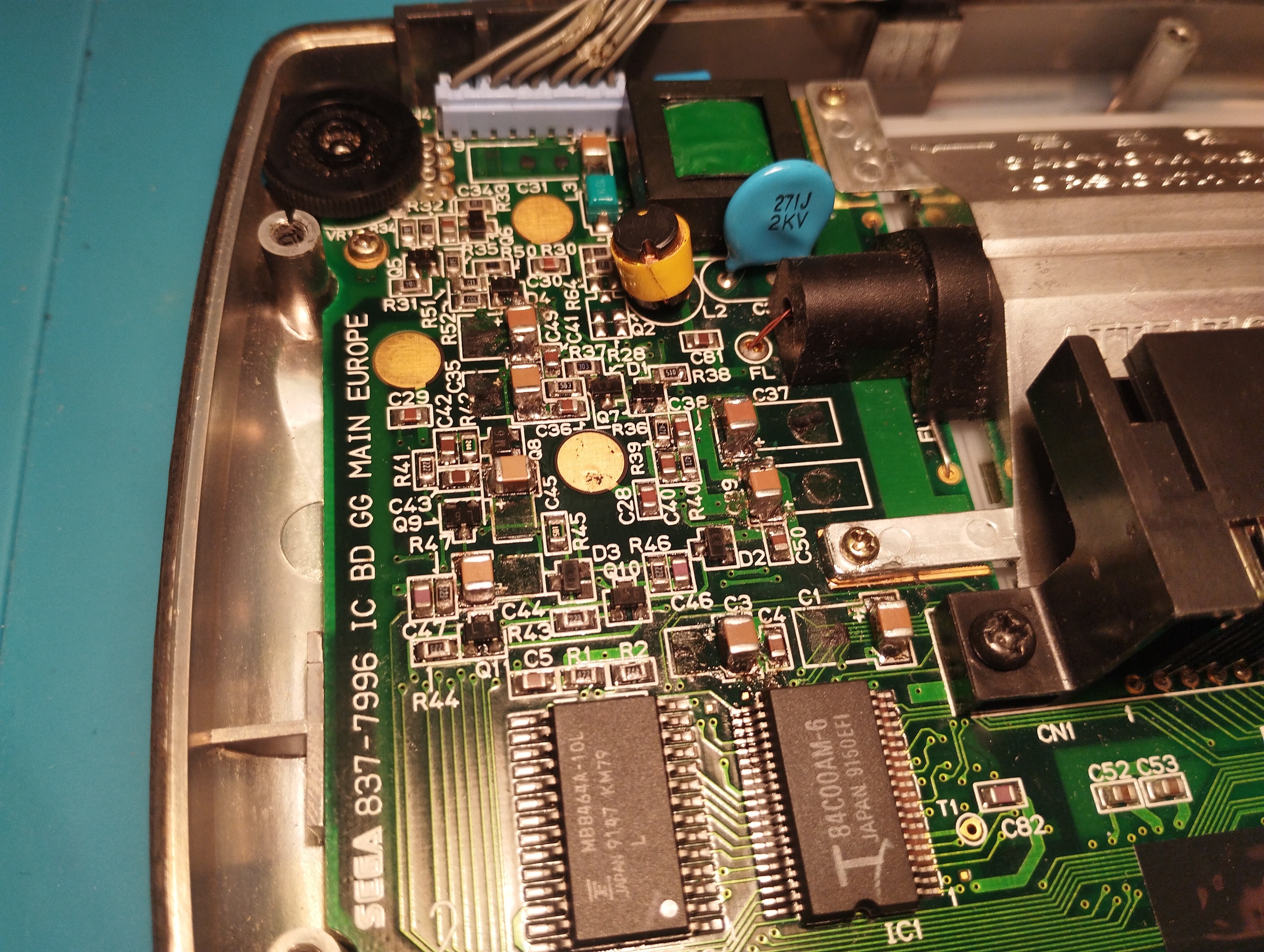
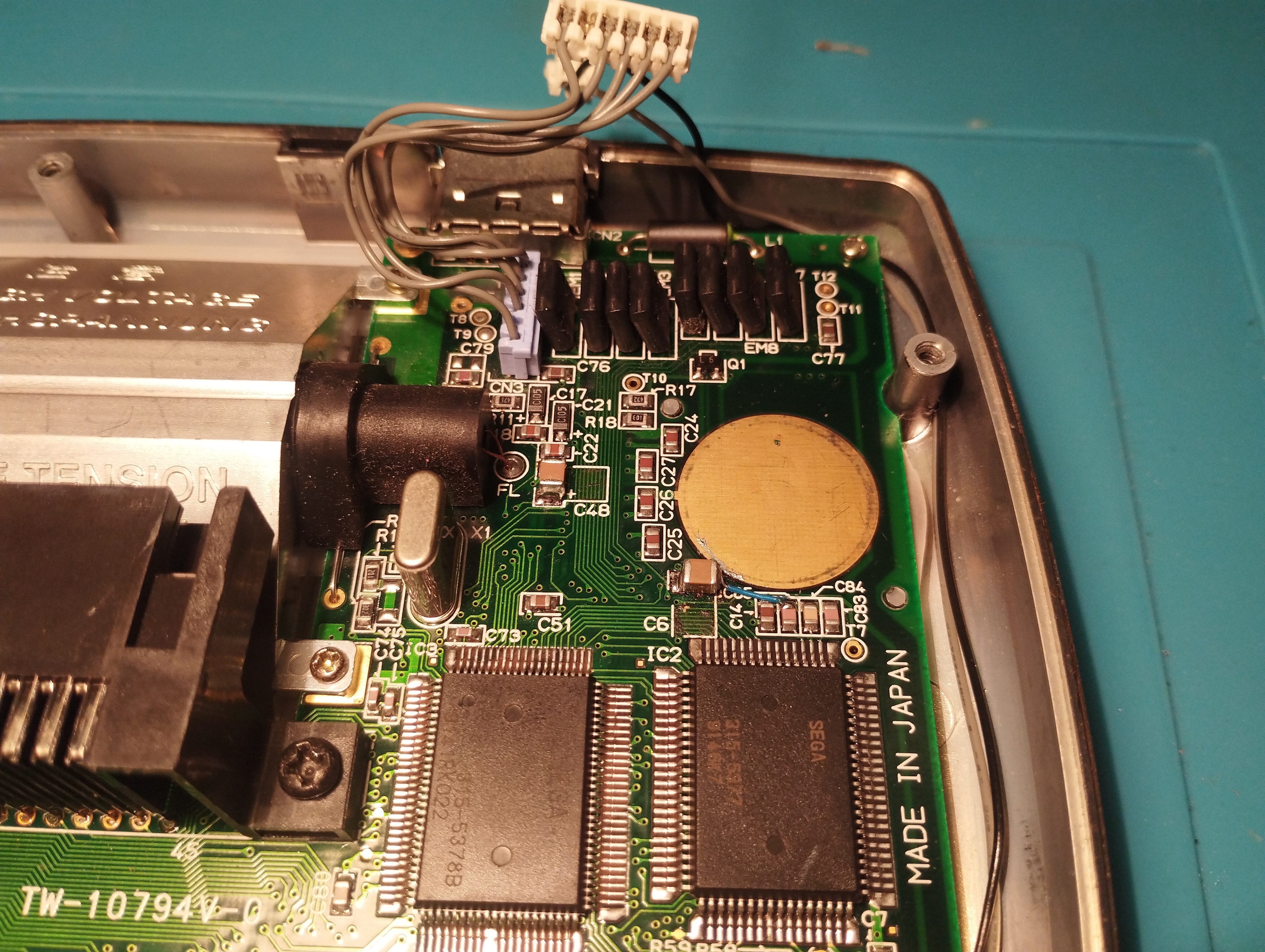
The soldering technique used this time consisted on the following steps:
- Tin one of the pads
- Pin one side of the capacitor to that pad
- After that apply solder to the other side
- Once done, rework the first pad by applying additional solder and adjusting the capacitor by applying heat to both pads if necessary
- Use a pair of tweezers to secure the capacitor in place while applying heat
Once recapped, test with working power and audio boards still don’t show image on the screen.
Repairing time
- 3 hours 30 minutes
State on boot
- Console enters the Red Light Boot state, required for further troubleshooting and repairs
- LCD doesn’t show image
- The fluorescent tube lights up but changing brightness doesn’t make a difference
- When tested with other working audio boards, game sound works
Next steps
Further checks on power board
- Maybe capacitors aren’t correctly connected or there’s a broken path
- Voltage regulator might be faulty
- Maybe other components (diodes) are also faulty?
Further checks on audio board
- Maybe capacitors aren’t correctly connected or there’s a broken path
Further checks on mother board
- Again, maybe some capacitor traces are broken or it’s just a non-functional screen
- Check LCD traces, see if there’s any discontinuity
Game boots and there’s sound, so unless there’s a major flaw not detected, this is a good candidate for an IPS screen